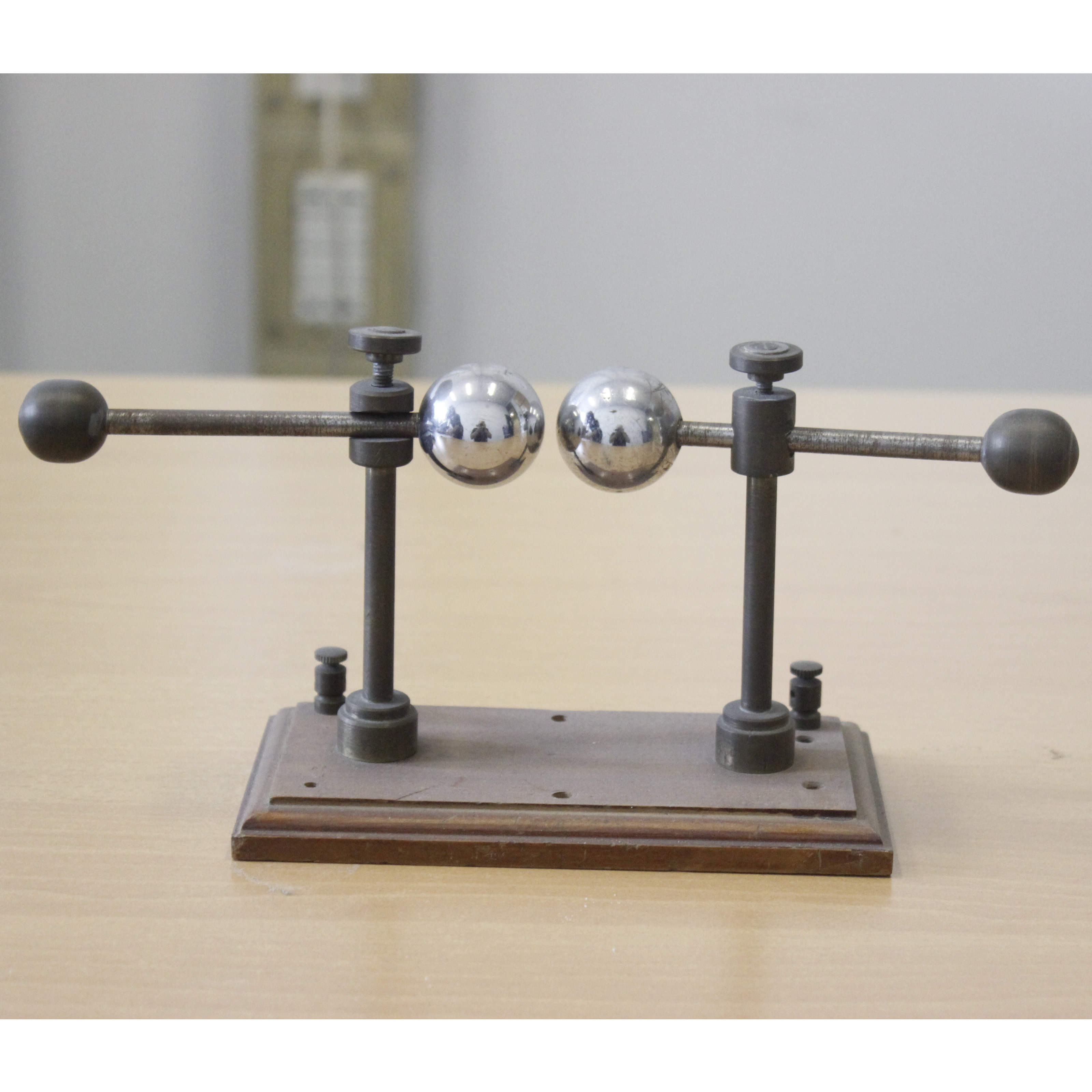
The spark gap is a device used to generate electrical discharges. It consists in two electrodes with adjustable distance, placed in a liquid or gaseous insulating medium. When the potential difference between the two electrodes reaches a certain value (called explosive potential), between them a spark charge is triggered.
INSIGHTS
The initial purpose of this apparatus concerns the generation of electromagnetic waves, whose existence was anticipated by James Clerk Maxwell in 1864 and verified experimentally by Hertz in 1886; from 1891 onwards Nikola Tesla used various types of spark gaps in his radio equipment. The
spark gap used in the first radio transmitters varied in construction according to the power requirements. Some were very simple, consisting of one or more spacers (static) connected in series, while others were significantly more complex. Since the discharges were hot and erosive, the
coating and cooling of the electrodes represented major issues. When the transmitter power was increased, cooling issues did as well.
Cooling refers to the action of extinguishing the electric arc previously emitted inside the spark gap.
This is considerably more difficult than the initial breakdown of the discharge in the distance (between the electrodes). A cold inactive spark gap does not contain ionized gas. Once the voltage between the electrodes reaches the breaking level, the gas molecules are ionized very quickly, creating a very hot electric arc, consisting in the flow of a large quantity of ions and free electrons
between the electrodes. The arc also carries part of the incandescent electrodes. The incandescent regions help to release electrons through the thermionic emission and to generate easily ionized metallic vapor. The mixture of ions and free electrons in the plasma is highly conductive, causing a sharp drop in the electrical resistance between the electrodes. This highly conductive arc requires efficient oscillating circuits with banks of capacitors. In any case, the oscillating current also supports the arc and, until it dies out, the bank of capacitors cannot be recharged for the next impulse.
The need to extinguish the arcs in high power transmitters led to the development of rotating spark gaps. These devices were used with alternating current generators, produced a more regular discharge and could use more power than conventional static spark gaps. The internal metal rotating
disk usually had a number of protrusions along the circumference. A discharge would have formed when two of the protrusions aligned with two external contacts carrying high voltage. The resulting arches were quickly compressed, cooled and stopped with the rotation of the disc.
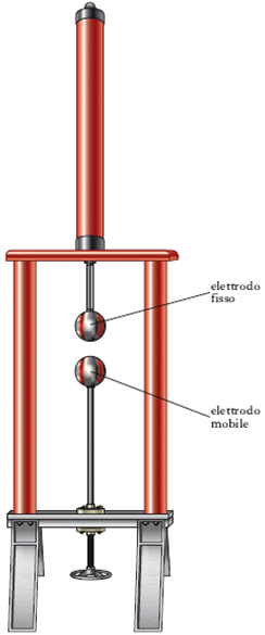
These devices can be used as voltmeters, to measure particularly high voltages: applied to the electrodes the voltage to be measured, the distance between them decreases until the arc; the value of this distance then goes back to that of the voltage applied by means of special conversion tables.
In physics and electrical engineering laboratories specialized in high voltage large spark gaps with dimensions of several meters are used.
Spark gap gauges are also used as switching (or ignition) voltage dischargers, devices that allow us to safeguard all our equipment from electrical discharges of atmospheric origin. When an overvoltage occurs, an electric arc is generated between the two electrodes through which excess energy is discharged.
Bibliography
https://it.wikipedia.org/wiki/Trasmettitore_a_spinterometro#Spinterometri
http://switchtothefuture.com/come-funziona-uno-scaricatore-di-sovratensione/ https://it.wikipedia.org/wiki/Spinterometro
http://www.treccani.it/enciclopedia/spinterometro/ https://www.electroyou.it/vis_resource.php?section=DomRisp&id=422